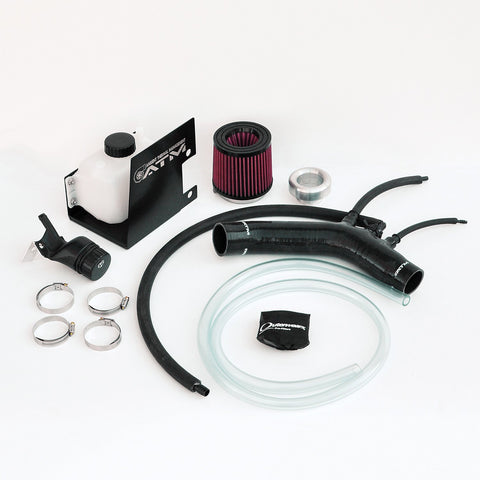
THE INTAKE SOLUTION FOR YOUR FMIC'D ABARTH!
Ambient Thermal Management is proud to offer yet another proven solution for those running a FMIC on their Fiat 500 Abarth and Turbo. Instead of sucking hot air in from the engine bay you can push in cold air from the fenderwell!
DEVELOPMENT- Prior to laying out an intake design for the Fiat 500 Abarth, ATM data-logged filter location temperatures under many circumstances. We searched for the coolest location which remained cool under the most driving variables. Just like the cowl location, the fenderwell proves to be a great area to draw in cold air to your engine. This is the perfect solution for those running a front mount intercooler.
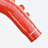
With the intake location moved to the passenger-side fenderwell, we then needed a conduit to flow the air. From past experience, we knew that multiple-ply silicone is superior to most other materials for its minimal thermal conductivity while remaining pliable. This means that it insulates from hot under hood temps while having some play for installation differences between cars and minimizing noises.
After choosing the best filter location and an optimal insulating duct, we now needed to optimize airflow. We developed a custom billet aluminum bellmouth for the filter to silicone connection. To complement this bellmouth, we had a custom filter manufactured to our specifications. This filter features maximum surface area and a laminar flow cone ensuring unrestricted performance.
The final result of all of this research and development is HORSEPOWER!!!!
HIGHLIGHTS
- Cleanable 8-Layer Cotton Media Filter w/water-repellant pre-filter Included
- Multi-ply silicone piping isolates colder Air Inlet Temperatures (AIT's) from hot underhood air temperatures
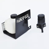
- Includes a complete windshield washer reservoir with a remote fill spout, compatible with the factory washer pump
- Features a machined (factory-like clip in) EVAP fitting, boost solenoid return fitting, and PCV fitting with extension hose.
- Quicker and better AIT recovery maintains a lower AIT overall.
-
Better flowing than the stock intake, resulting in faster turbo spooling and a higher torque curve.
-
Increases intake air density/WHP and decreases susceptibility to detonation.
Finish
Available in Red or Black Silicone
Testing:
The filter locations tested are:
- OEM (stock intake)
- Under the hood (in the engine bay)
- Behind the firewall/Under the cowl
The driving variables tested are:
- Cruising @ 40mph
- Several wide open throttle runs at set distances in specific gears
- Cruising @ 55mph
- Sitting idle for 5 minutes
Additional temperatures taken are:
- Ambient (outside) air temperature
- Air temperature in the engine bay (taken on the passenger’s side of the engine)
- Turbo inlet air temperature (taken at the boost solenoid return port)
- Intake manifold air temperatures.
Below are the results of the test. This chart and line graph displays the difference (Delta Δ Temperature) between the turbo inlet air temperature and the outside ambient air temperature. The lower numbers show that there is little rise in air temperature from the outside ambient air. Therefore the filter location is better isolated and the intake system better insulates the intake air from underhood heat. The cowl location proves to be the optimal filter location, very similar to the fenderwell. Then followed by the OEM intake, and lastly, under the hood.
Performance:
In the dyno plots below, we are comparing the best results in the series of dynos for both intakes. Our Holey Cowl intake yielded an average increase of 17WHP and 17WTQ over the stock intake. With the short distance and laminar flow to the turbo that the Ram Air intake provides, you can expect even better results! WHP and WTQ peak difference are 13WHP and 29WTQ. These are real gains over the stock unit by the intake's ability to make power and maintain it in heat soak scenarios!
- Installation Video: https://www.youtube.com/watch?v=cHFXGtcdNZ4
- Remove plastic connector from the back of the airbox (see 1st pic below). Connect back to vehicle lines and connect to the end of the 3/8" intake hose (see 2nd pic below).
- Remove airbox sensor held in by two torx screws - Locate included "T" along 5/8" line, cut and connect as shown (hose clamps optional).


